To determine the optimal locations for sensor placement in a water treatment plant, we aim to monitor all water flows using the fewest number of sensors. This can be achieved by constructing a flow graph, where:
Nodes represent system components (e.g., equipments, junctions).
Edges represent water flows between these components.
We generate this graph from an RDF-based model of the plant. The graph abstraction implemented here is based on WWTP1, described in the paper “Optimal flow sensor placement on wastewater treatment plants” by Villez et al. (2016). We can identify a minimal set of sensor placements that covers all flows in the system.
Graph Construction Using SPARQL Rules
In the RDF based model, equipments are connected indirectly through multiple steps.
Each connection flows from:
Equipment -> Outlet Connection point -> Pipe -> Inlet Connection Point -> EquipmentThis structure makes it complicated for optimal sensor placement. Therefore we simplify the topology as described by Villez et al. (2016), traversing only the most essential paths that reflect actual flow of material through pipes using SPARQL queries. We follow the connectsFrom and connectsTo relationships, to bypass intermediate nodes like connection points or junctions.
Ensuring Graph Completeness
To make the graph fully closed (i.e., all flows are measured), we introduce a special node called Environment, which represents everything external to the system. This connects all inflows and outflows to a common endpoint.
This Prevents unconnected “open ends” where water appears or disappears which enforces flow conservation, and enables accurate modeling for optimal sensor placement.
We use two SPARQL Rules (Pipe Rule and Enviroment Rule) to extract the necessary structure from the RDF model and simplify it into a usable flow graph. These SPARQL rules:
Identify connections between equipments and pipes.
Ignores non-essential intermediary nodes.
Attach unconnected flow endpoints to the
Environment.
Visual Transformation Overview
Before: Raw RDF Graph
(equipment →Outlet Connection points → pipe → Inlet Connection points → equipment)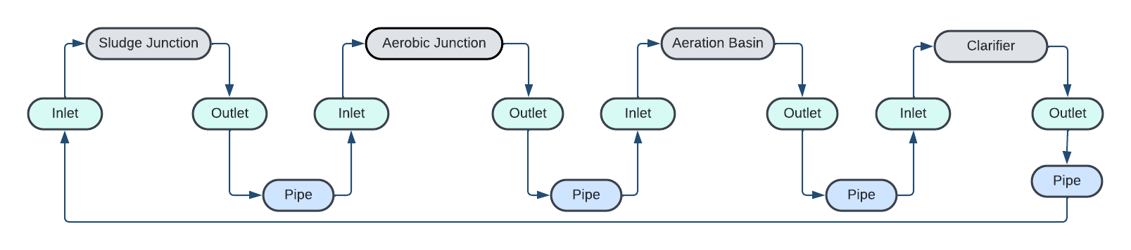
After: Simplified Flow Graph
(direct connections from one equipment to another, and environment closure)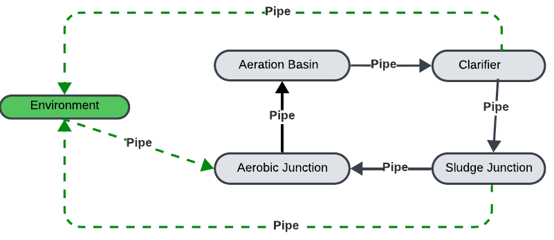
Rule 1: Pipe Rule
Simplifies the topology by removing intermediate connection points and directly links functional components.
PREFIX s223: <http://data.ashrae.org/standard223#>

SELECT ?from ?conn ?to WHERE {
    ?conn s223:connectsFrom ?from .
    ?conn s223:connectsTo ?to .
}
Step-by-step Explanation
PREFIX s223:
Defines the shortcut for the ASHRAE 223P ontology namespace.SELECT
?from?conn?totells SPARQL to return the source, pipe, and destination?conns223:connectsFrom?fromidentifies where the connection starts?conns223:connectsTo?toidentifies where it ends
Rule 2: Environment Rule
Links unconnected inlets and outlets to the Environment node while preserving flow directionality.
PREFIX s223: <http://data.ashrae.org/standard223#>

SELECT ?from ?conn ?to WHERE {
    {
        ?to_orig rdf:type s223:OutletConnectionPoint .
        ?from s223:hasConnectionPoint ?to_orig .
        FILTER NOT EXISTS {
            ?to_orig s223:connectsThrough ?conn_orig
        }
        BIND("connects_to_env" AS ?conn)
        BIND("Environment" AS ?to)


    }
    UNION
    {
        ?from_orig rdf:type s223:InletConnectionPoint .
        ?to s223:hasConnectionPoint ?from_orig .
        FILTER NOT EXISTS {
            ?from_orig s223:connectsThrough ?conn_orig
        }
        BIND("connects_to_env" AS ?conn)
        BIND("Environment" AS ?from)
    }
}
Step-by-step Explanation
SELECT ?from ?conn ?to
Instructs SPARQL to return three values for each match:?from– the upstream device?conn– the literal string"connects_to_env"?to– theEnvironment
Branch 1 (Outlet):
?to_orig rdf:type s223:OutletConnectionPoint
Finds every outlet connection point.?from s223:hasConnectionPoint ?to_orig
Identifies every outlet connection point’s source device.FILTER NOT EXISTS { ?to_orig s223:connectsThrough ?conn_orig }
Ensures no pipe is fedby this outlet.BIND("connects_to_env" AS ?conn)
Labels the relationship of device and EnviromentBIND("Environment" AS ?to)
Marks the endpoint asEnvironment.Resulting connection:
Equipment-> connects_to_env -> Environment
Branch 2 (Inlet):
?from_orig rdf:type s223:InletConnectionPoint
Finds every inlet connection point.?device s223:hasConnectionPoint ?from_orig
Identifies every inlet connection point’s source device.FILTER NOT EXISTS { ?from_orig s223:connectsThrough ?conn_orig }
Ensures no pipe feeds this inlet.BIND("connects_to_env" AS ?conn)
Labels the relationship of device and EnviromentBIND("Environment" AS ?from)
Marks the source asEnvironment.Resulting connection:
Environment -> connects_to_env -> Equipment
This will output a simplified RDF graph ready for sensor placement optimization.
- Villez, K., Vanrolleghem, P. A., & Corominas, L. (2016). Optimal flow sensor placement on wastewater treatment plants. Water Research, 101, 75–83. 10.1016/j.watres.2016.05.068